PSI Explained: Safety Systems
Title 8 CCR §5189(d)(3)(A)(8) and Title 29 CFR §1910.119(d)(3)(i)(H) requires that “information pertaining to the equipment in the process shall include: Safety systems (e.g. interlocks, detection or suppression systems)”. At minimum, Safety Systems documentation must identify and summarize all Safety Systems associated with the chemical process. Once developed, this documentation will serve as a useful tool to provide training to facility personnel in the proper use and understanding of these systems.
The following is a summary list of Safety Systems that are typically associated with an ammonia refrigeration system along with best practices for developing Safety System documentation. We recommend including pictures of each Safety System to assist in better understanding the associated components.
Ammonia Detection System
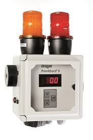
Ammonia detection is a first line of defense against exposure a refrigerant leak. At minimum, we recommend that documentation include a brief functional description of the detection system which answers the following questions:
- How many sensors are installed?
- Where are the sensors located?
- At what concentration do the sensors activate an alarm?
- What does the alarm(s) do?
- What components are interlocked with the detection system?
You can read our previous posts on ammonia detection here and here.
Emergency Control Box
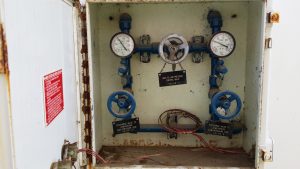
Emergency Control Boxes (ECB) are legacy requirements of the Mechanical and Fire Code. The purpose of an ECB is to provide a location to manually control the system pressure through equalization and refrigerant evacuation. Although ECBs have not been required in a code since 2003 (NFPA 1), many refrigeration systems built prior to (and since) that time have an ECB installed. As such, it is recommended that a short description of the operation of the ECB be included. Typically, this will look something like this:
The Emergency Control Box was installed in accordance with ANSI/IIAR 2 and the Fire Code at the time of construction. The control box contains three (3) valves.
- Valve #1: High Side Discharge Valve
- Valve #2: Low Side Discharge Valve
- Valve #3: High to Low Pressure Control Valve
Opening Valve #1 will evacuate the process through the high pressure side of the system. Opening Valve #2 will evacuate the process through the low pressure side of the system. Opening Valve #3 will equalize the high and low pressure portions of the system.
The Emergency Control Box is seldom used in a refrigeration system, but has been installed for rare emergency situations to reduce overpressure.
You can read our previous post on Emergency Control Boxes here and here.
Emergency Pressure Control System
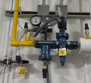
Emergency Pressure Control Systems (EPCS) replaced Emergency Control Boxes (ECBs) in the International Fire Code (IFC) in 2006. As a result, many newer refrigeration systems are equipped with an EPCS which serves to automatically equalize a higher-pressure side of the system with a lower-pressure side if overpressure occurs. If an EPCS is installed, the Safety Systems documentation should include a brief description of the system operation. Sample text is included below:
The emergency pressure control system was installed in accordance with ANSI/IIAR 2-2014 and the 2016 California Fire Code at the time of construction.
The Emergency Pressure Control System (EPCS) operates as follows:
- EPCS is activated at not greater than 90% pressure relief valve setting (e.g. 270 psig or less) [ANSI/IIAR 2-2014 Appendix I.4.5.3]
- Upon activation, all compressors are stopped by a means that is independent of all other safety controls [ANSI/IIAR 2-2014 Appendix I.4.5.6]
- Upon activation, cross-over valve is opened [ANSI/IIAR 2-2014 Appendix I.4.5.6]
- Upon activation, a signal is provided to personnel responsible for refrigeration system maintenance [ANSI/IIAR 2-2014 Appendix I.4.5.7]
- EPCS remains active until manually reset [ANSI/IIAR 2-2014 Appendix I.4.5.8]
- EPCS crossover isolation valves are locked open [ANSI/IIAR 2-2014 Appendix I.4.4.2]
The emergency pressure control system is seldom used in a refrigeration system, but has been installed for rare emergency situations.
You can read our previous post on Emergency Pressure Control Systems here.
Pressure Relief Valves
Pressure relief valves have been discussed in detail in our previous post on Relief System Design and Design Basis. It is appropriate, however, to include a brief description of relief valves in the Safety Systems documentation as well, since relief valves serve an important safety function in protecting equipment from overpressure. Example verbiage for the Safety Systems documentation is included below:
All ASME vessels and positive displacement compressors are equipped with pressure relief valves. The high side of the system relieves at 250 psig while the low side of each system relieves at 150 psig. All pressure relief valves vent to the atmosphere.
In addition to relief valves, if the relief system is equipped with a device which notifies personnel that a relief valve has lifted, it is suggested that a description of the device be included in the Safety Systems documentation as well. Typically, the devices are of one of the following types:
- Vent Line Sensor – A device that detects ammonia in the relief valve discharge termination piping and sends an alarm signal to notify personnel.
- Rupture Disc and Gauge – A device that is installed upstream of a relief valve and breaks at predetermined set pressure. A rupture disc will be equipped with a gauge or electronic sensor to provide notification that the rupture disc and associated relief valve have lifted.
- Pressure Transducer/Switch – A device, when installed on the relief valve discharge termination pipe, will provide an alarm signal of a pressure surge, indicating that a relief valve has lifted.
- Relief Vent Indicator – The TattleTM relief vent indicator (RVI) is a mechanical device that works as follows: Indicator flags are mounted to the shaft of the RVI on the outside of the housing. A paddle is set such that any sudden flow in the relief vent line pushes it down simultaneously raising the flags which then provides a clear signal that a relief valve has lifted. Stoppers mounted to the exterior prevent the flag/shaft from rotating more than the 90º swing.
Computer Control System / PLC / Switch and Light Panel
Most refrigeration systems are equipped with computer controls, PLC, switch and light panels, etc. As such, it is recommended that the Safety Systems documentation include a brief description of the alarm sequences that are integral to the control logic.
- What circumstances will result in an alarm?
- What happens when an alarm signal is activated?
- How are alarm signals reset?
Diffusion Tank
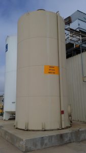
Often in California, relief valve discharge piping will terminate into a Diffusion Tank. Diffusion Tanks were required by the Uniform Mechanical Code (UMC) from 1994 to 2012. As such, most facilities built in California during those years are equipped with such a tank. The Safety Systems documentation must include a brief description of the Diffusion Tank. Sample text is included below:
All pressure relief devices are piped to a diffusion tank sized according to the Uniform Mechanical Code at the time of construction. This tank helps mitigate many of the hazards associated with the release of ammonia through a pressure relief valve.
You can read our previous post on Ammonia Diffusion Tanks here.
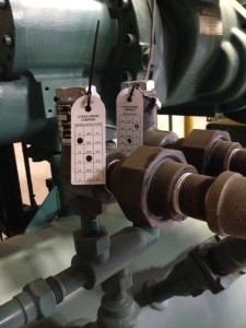
Compressor Safety Devices
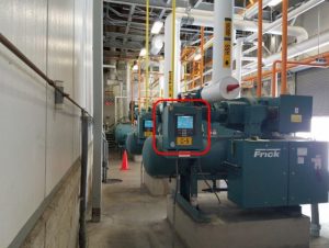
Every closed-circuit mechanical refrigeration system is equipped with compressors which serve to increase the pressure of the low temperature vapor so that the heat absorbed in the refrigerant can be rejected to the environment. Compressors packages contain numerous safety devices, but at minimum, the Safety Systems documentation must include a short description of the following safety devices:
- High discharge pressure cutout
- Low suction pressure cutout
- Oil pressure cutout
These devices can be of the mechanical-type (as typically installed on reciprocating compressors) or of the electronic type (as typically installed on screw compressors). It is best practice that the description in the Safety Systems documentation specify what occurs when the alarms are activated. Sample text is included below:
Each compressor has numerous safety devices to protect the compressor and the associated equipment. The following table summarizes the safety systems built into each compressor package:
- High Pressure Cutout – The High Discharge Pressure Cutout will shut down the compressor if the discharge pressure equals or exceeds the set point.
- Low Pressure Cutout – The low pressure cutout will shut down the compressor if the suction pressure is equal to or less than this set point.
- Oil Pressure Cutout – The oil pressure cutout will shut down the compressor if the oil pressure equals or exceeds this set point.
High Level Float Switch / Level Controller
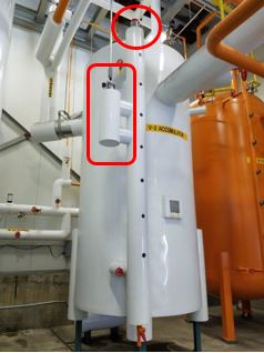
Vessels that supply vapor to the suction of compressors (suction accumulators, intercoolers, and recirculators) must be equipped with a high level float switch to help prevent liquid from entering and damaging the compressors. The Safety Systems documentation typically includes a brief description of the function of the high level float switch(es) which summarizes what occurs when a high level float switch is tripped.
The suction accumulator is equipped with a high level float switch that is wired to shut down the compressors in the event of a high level situation. This prevents liquid ammonia from entering the compressor.
Often these vessels may also be equipped with a level probe and controller to provide real-time monitoring of the liquid level in the vessel. Level controllers also provide high-level protection. As such, they should be included in the Safety Systems documentation as well. Refer to the sample text below as an example:
The liquid recirculator is equipped with a level controller to control the liquid ammonia level in the vessel. The level controller is equipped with high level, control level, and low level set points.
Main Liquid Feed Shut-Off Valve (King Valve)
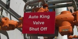
Main liquid shut-off valves (e.g King Valves) serve an important safety function during emergency situations. As such, it is important that the location and function of main shut-off valves be summarized in the Safety Systems documentation.
The high pressure receiver is equipped with a main liquid feed shut-off valve (king valve) that is clearly labeled and can be used to stop the flow of ammonia throughout the system.
Emergency Refrigeration Switch
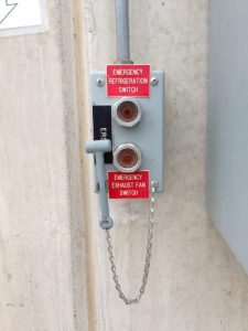
Often ammonia refrigeration systems are equipped with remote emergency shut-off switches (E-stops). These switches provide a location to shut off the refrigeration machinery from outside the machinery room. Since they serve an important safety function, it is necessary that they be included in the Safety Systems documentation accordingly. Sample text for an E-stop is included below:
The principal entrance to the machinery room is equipped with an emergency refrigeration switch that controls power to the refrigeration machinery inside the machinery room. The switch can be activated in an emergency using the hammer next to the switch to break the switch glass.
You can read our previous post on E-stops here.
Emergency Eyewash and Shower Station
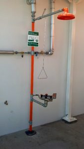
Emergency eyewash and shower stations provide necessary mean of emergency decontamination to chemical exposure. As such, it is recommended that the Safety Systems documentation include a brief description of the quantity and location of emergency eyewash and shower stations onsite. For example:
Three (3) emergency eyewash and shower stations are installed onsite: (1) inside the machinery room, (2) outside the machinery room, and (3) next to the forklift charging area.
You can read our previous posts on emergency eyewash and shower stations here, here, and here.
Labeling and Signage
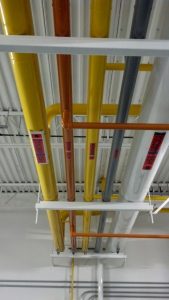
While not a bona fide “Safety System”, labels and signs serve an important safety function and can be included in the Safety Systems documentation as well. Ideally, the documentation will be accompanied by pictures which illustrate the types of labels and signs that can be found on the chemical process piping and equipment.
We’ve addressed labeling and signage in several of our previous blog posts:
- Ammonia Pipe Labels
- NFPA 704 and Ammonia
- Labeling an Ammonia Receiver
- Pipe Labeling – ASME A13.1 Update
Other Safety Systems
Other safety systems that are not directly related to the ammonia refrigeration system, but may be needed during an emergency and therefore should be included on the Safety Systems documentation include:
- Main Electrical Shut-Off
- Fire Extinguisher
- Main Gas Shut-Off
- Main Propane Shut-Off
- Fire Sprinkler System
- Main Water Shut-Off
- Fire Alarm Pull Station
- Wind Sock
- Fire Hydrant
For each of these items, it is recommended that the Safety Systems documentation include a picture along with a brief description of where the device is located.
Leave a Reply