PSI Explained: Relief System Design and Design Basis
 Relief System Design and Design Basis is one of the most commonly inspected components of Process Safety Information (Title 8 CCR §5189(d)(3)(A)(4) and Title 29 CFR §1910.119(d)(3)(i)(D)). This documentation, when prepared correctly, will describe the basis by which a relief system was designed. Notice that the requirement is not limited to “relief valves”, but rather applies to the entire relief system which includes termination piping. Compliant Relief System Design and Design Basis documentation will include at least the following information:
- Basis of the relief system design (code/standard used)
- Name of each piece of equipment required to be protected by relief valves
- Specifications for each piece of equipment required to be protected by relief valves (e.g. length and diameter of pressure vessels)
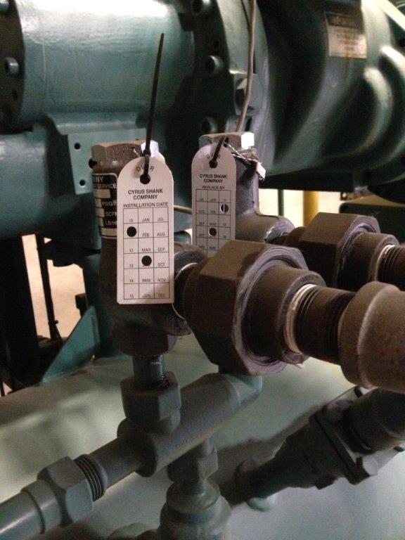
- Manufacturer / model of each relief valve
- Set pressure (psig) of each relief valve
- Capacity (scfm or lb/min) of each relief valve
- Analysis proving that the set pressure and capacity are adequate
- Diameter and length of discharge termination piping
- Analysis proving that the discharge termination piping does not adversely affect relief valve performance
For an ammonia refrigeration system, Relief System Design and Design Basis is typically governed by the mechanical code and/or IIAR 2 at the time of construction. ANSI/IIAR 2-2014 has dedicated an entire chapter (Chapter 15) to the topic of overpressure protection. The following list is a summary of some of the often cited relief valve requirements:
- Refrigeration systems shall be protected by not less than one pressure relief device. [15.2.1]
- Pressure relief devices intended for vapor service shall be connected above the highest anticipated liquid ammonia level. [15.2.4]
- The set pressure for a pressure relief device shall not exceed the design pressure of equipment protected by the device. [15.2.6.1]
- The required discharge capacity of a pressure relief device for each pressure vessel shall be determined by the following equation:
C = ƒ · D · L (lb/min)
Where
C = required discharge capacity of the relief device, lb air/min
ƒ = capacity factor of the relief device, which is 0.5 (0.04) for ammonia [0.5 is in inch-pounds (IP)]
D = outside diameter of vessel, ft
L = length of vessel, ft.
[15.3.7.2.1] - The size of the discharge pipe from a pressure relief device or fusible plug shall be no less than the outlet size of the pressure relief device. The minimum size and total equivalent length of common discharge piping downstream from each of two or more relief devices shall be determined based on the sum of the discharge capacities of all relief devices that are expected to discharge simultaneously, with due allowance for the pressure drop in each downstream section. [15.4.4]
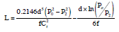
- The design backpressure in the discharge piping at the outlet of pressure-relief devices and fusible plugs, discharging through a single relief device to atmosphere, shall be limited by the allowable equivalent length of piping determined by Equation 15.5.1.1.1(1) or 15.5.1.1.1(2).
Where,
L = equivalent length of discharge piping, ft [m];
Cr = rated capacity as stamped on the relief device in lb/min [kg/s], or in SCFM multiplied by 0.0764, or as calculated in ANSI/ASHRAE 15, Section 9.7.7 for a rupture member or fusible plug, or as adjusted for reduced capacity due to piping as specified by the manufacturer of the device, or as adjusted for reduced capacity due to piping as estimated by an approved method;
ƒ = Moody friction factor in fully turbulent flow [See A.15.5.1.1.1(1) and (2)];
d = inside diameter of pipe or tube, in [mm];
ln = natural logarithm;
P2 = absolute pressure at outlet of discharge piping, psi [kPa];
P0 = allowed back pressure (absolute) at the outlet of pressure relief device, psi [kPa]. - The termination of pressure relief device discharge piping relieving to atmosphere shall be not less than 15 ft (4.6 m) above grade and not less than 20 ft (6.1 m) from windows, ventilation intakes, or exits. [15.5.1.2]
- The discharge termination from pressure relief devices relieving to atmosphere shall not be less than 7.25 ft (2.2 m) above a roof that is occupied solely during service and inspection. Where a higher adjacent roof level is within 20 ft (6.1 m) horizontal distance from the relief discharge, the discharge termination shall not be less than 7.25 ft (2.2 m) above the height of the higher adjacent roof. [15.5.1.3]
In general, relief system analysis is performed using spreadsheets. For those desiring, a more robust analysis, the Industrial Refrigeration Consortium’s Safety Relief Vent Tool allows a user to model their relief system and then to test the system for compliance with respect to various relief valve lifting scenarios.
![]()
Note: Please check out other blogs that we have posted on the topic of relief valves / overpressure protection:
- Relief Valve Piping System Design Scenario
- Relief Valves
- Relief Valve Replacement (Dual Assembly)
- Relief Valves Protecting Multiple Vessels
- Stop Valves on Relief Valves
- Compressor Relief Valves
- Relief Valve Discharge Piping
- Condenser Relief Valves
- Relief Valves Discharging Back into a Refrigeration System
good day Team, nice to see and read this info, i would like please to share with me the documents format for Relief system design and design basis, currently we are working to devlop this documents for all production station.
There is no one approved format. Many engineers use spreadsheets and there is also software available from the Industrial Refrigeration Consortium (IRC) that you can use to verify compliance and develop documentation.