Excerpts from ANSI/IIAR 4-2015
After years of hard work, IIAR has recently published two (2) new refrigeration standards:
- ANSI/IIAR 4-2015 Installation of Closed-Circuit Ammonia Refrigeration Systems
- ANSI/IIAR 8-2015 Decommissioning of Closed-Circuit Ammonia Refrigeration Systems
In this blog and the next, I will summarize each of the standards and provide excerpts that are important to be aware of. Be sure to purchase these important documents from the IIAR website.
IIAR 4 – Installation of Closed-Circuit Ammonia Refrigeration Systems
I had the privilege to be a member of the subcommittee responsible for writing IIAR 4. As a committee, the first step we took in writing this standard was to “steal” all language regarding installation from ANSI/IIAR 2-2008 Addendum B. This became the foundation of the new standard. (Note: IIAR 2 is currently being rewritten from a design and installation standard to a design-only standard).
Here are some highlights from IIAR 4:
Scope (Section 2): The standard applies to the “installation of closed-circuit ammonia mechanical refrigeration systems…“. Ammonia absorption refrigeration systems and equipment installed prior to the standard being published should not be considered subject to the standard.
General Requirements (Section 5): Most of Section 5 is consistent with what has been best practice for our industry all along. §5.1 requires competency for those involved in the installation process. §5.3 includes general material requirements (compliance with ASME B31.5 and B&PV Code Section VIII) and reminder that copper and copper alloys cannot be used.
Equipment accessibility is clearly addressed in §5.4.1 “All equipment, pipe, fittings, valves and components shall be positioned to insure that appropriate clearances are provided for specific accessibility and service requirements and allow for safe egress in the event of an emergency.”
Some important clarifications regarding component location are made in §5.4 as well
- §5.4.7 requires components to “be installed in such a manner that they are protected from physical and environmental damage.”
- §5.4.8 requires piping that crosses an open space to be at least “7.25 ft (2.2 m) above the floor” unless the ceiling is less than than 7.25 ft high.
- 5.4.9 requires that “passages shall not be obstructed by refrigerant piping.”
The bullet points above are common sense, but now clearly stated in standard language.
Component-Specific Requirements (Sections 6-9, 11.1): Sections 6-9 and 11.1 address the specific requirements for Compressors, Condensers, Evaporators, Pressure Vessels, and Pumps. In general, each of the above-named sections have the same requirements:
- Rotating components must be properly guarded (§6.1.1, §7.1.1, §8.1.1, §11.1.1)
- Support structures must be adequate (§6.1.2, §7.1.2, §8.1.2, §9.1.1, §11.1.2)
- Component installation must not allow for excessive vibration (§6.1.5, §7.1.3, §8.1.3, §11.1.5)
- Electrical wiring must conform to NFPA 70: National Electric Code (§6.1.6, §7.1.4, §8.1.4, §9.1.3, §11.1.6)
Piping and Valve Installation (Section 10): In the main, Section 10 restates what is currently required in ANSI/IIAR 2-2008 Addendum B. Several important nuances should be understood:
- Hot tapping is not prohibited (§10.1.4)
- 1/2″ and smaller pipe is not prohibited (§10.3.2). This is an important clarification because ANSI/IIAR 2-2008 Addendum B §10.2.3 states that “the use of 1/2 inch and smaller pipe is not recommended.”
- Relief valve discharge piping that terminates into the atmosphere or a diffusion tank is not considered part of the closed-circuit refrigeration system (§10.3.3.2). Hydrostatic relief valve discharge piping that terminates back into the system is considered part of the closed-circuit refrigeration system (§10.3.3.1). The implications of this are that galvanized or un-galvanized ASTM A120, A53/A120, or A53 – Type F piping are permitted on atmospheric relief piping.
- Stop valves must be capable of being locked out (§10.4.4)
Liquid Level Indicators (Section 11.2): Section 11.2 addresses visual liquid level indicators. §11.2.1 covers bull’s-eye type indicators and §11.2.2 covers tubular glass and flat armored glass. Requirements are consistent with what has historically been required for tubular glass. In regard to bull’s eye type indicators, §11.2.1.1 requires indicator inspection prior to installation and replacement of “any indicator found to have a scratch, chip or any defect”.
Insulation (Section 12, Appendix B): Section 12 requires pipes and components “whose surface temperature is expected to be at or below the dew point temperature” to be insulated. An exception is allowed for valve groups to facilitate maintenance. Appedix B (informative) is an excellent resource regarding the fundamentals of insulation, material selection, corrosion under insulation, and other best practices.
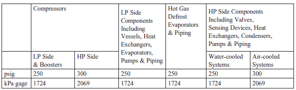
Testing of Installation (Section 13, Appendix B): Section 13 requires field leak testing, evacuation, and dehydration after completion of the installation. The procedures followed must be consistent with ANSI/IIAR 5-2013 and ASME B31.5 §538. The following test pressures must be used:
That wraps up the fly-by summary of IIAR 4. Next week, I will summarize IIAR 8 in a similar fashion.
Leave a Reply