Atmospheric Termination of Relief Valve Discharge Piping
Since ammonia diffusion tanks were removed from the California Mechanical Code in 2016, atmospheric termination of relief valves has once again become a viable strategy for ammonia refrigeration systems. The question that often arises, however, is what constitutes “safe” termination to atmosphere. ANSI/IIAR 2-2014 §15.5.1 outlines five requirements for proper atmospheric termination:
- Discharge pipe must be sized to prevent excessive back pressure [§15.5.1.1]
- Termination must be 15 ft above grade and 20 ft from openings into a building [§15.5.1.2]
- Termination must be 7.25 ft above a roof or platform surfaces such as condenser catwalks that are occupied solely during service and inspection [§15.5.1.3 and §15.5.1.4]
- Termination must be directed upward and arranged to avoid negatively impacting personnel [§15.5.1.5]
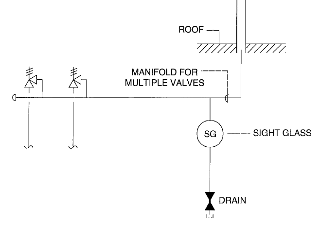
- Provision for draining moisture from the discharge piping must be provided [§15.5.1.6]
While it is beyond the scope of this blog to exhaustively consider relief valve termination piping, it’s worthwhile to explore options relative to Item 4 in the list above. The language used in ANSI/IIAR 2-2014 §15.5.1.5 seems to indicate that the point of termination must always be vertical to achieve compliance. The text reads:
ANSI/IIAR 2-2014 §15.5.1.5
The termination of the discharge shall be directed upward and arranged to avoid spraying ammonia on persons in the vicinity.
Informative Appendix A helps to clarify the intention of the requirement and more specifically, what is meant by “directed upwards”.
ANSI/IIAR 2-2014 A.15.5.1.5
The termination of discharge is considered the final several feet of the relief piping. The vent end point of relief piping may include a design to prevent rain and snow from entering. Many designs provide a method to prevent rain and snow from entering. The design at the vent end point may be a “tee” diffuser, a “double 45 degree” diffuser, a “bull’s horn” diffuser, a “spring self-closing flapper cap,” or a “sock hood cover.” The “spring self-closing flapper cap” is used on natural gas and tractor exhausts. The “sock hood cover,” which is typically bright safety yellow, orange, or red in color, has a light flexible string attached between the hood and the relief pipe stack for its containment if lifted. Another design method that may be incorporated has a fully open vent end point that is the “exterior stack extension” diffuser. The “exterior stack extension” diffuser has the relief termination piping extended on center up and into a separate larger-diameter stack extension. Any rain and snow that gets into the extended larger-diameter stack draws to the internal surface and drops down and drains out drain hole(s) at the bottom. This keeps the rain and snow from getting into the relief termination piping that is on center internally.
After reading the text of A.15.5.1.5, it becomes clear that it was not the intention of IIAR to handcuff installers by only allowing a single method of relief valve termination. While many engineered approaches can be both safe and compliant, the following list summarizes common atmospheric relief valve discharge termination pipe arrangements:
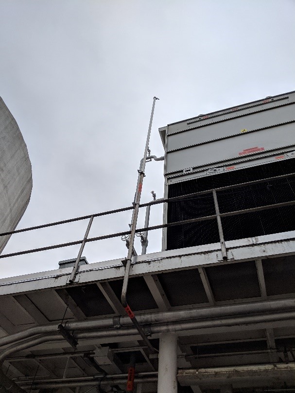
1. “Tee” Diffuser
The “tee” diffuser is listed in ANSI/IIAR 2-2014 A.15.5.1.5 and also included as an example of proper termination in the IIAR Ammonia Refrigeration Piping Handbook (Figure 6-3).
This simple design prevents rain and snow from entering the discharge pipe by the installation of a tee at the termination point which forces all ammonia to escape the pipe horizontally.
2. Rain Cap
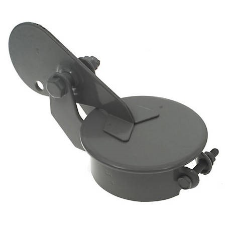
A rain cap is a simple device which prevents water from entering a discharge pipe, while still allowing for ammonia to disperse vertically. When a relief valve lifts, the pressure will cause the cap to open, releasing ammonia to atmosphere. Once the release has stopped, the cap will return to its original position. These devices are inexpensive and easy to install, thus serving as a good option for atmospheric termination.
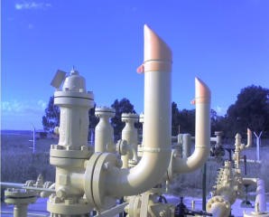
3. Weather Cap
Similar to the rain caps, these simple devices prevent rain and snow from entering the discharge pipes. The weather cap, is essentially a “sock” which covers the termination pipe and would be blown off when a relief valve lifts. These devices have an added benefit providing a visual indication that a relief valve has lifted, since a weather cap will not reset itself after a relief valve has lifted.
4. Vertical Pipe
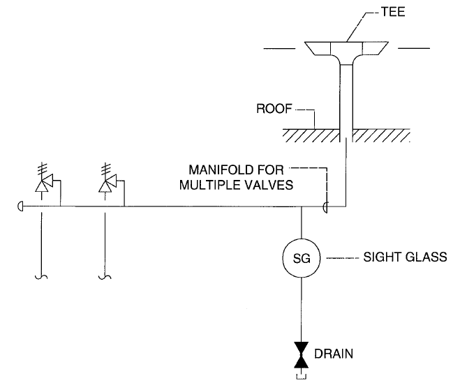
A simple option is to discharge the ammonia vertically through an open pipe. When using this method, it is essential that a water drain valve be readily available to remove any rain water that may collect in the pipe.
I attended an IIAR webinar yesterday on mechanical integrity. During the webinar, Tony Lundell stated that “T’ stacks are now noncompliant.
The 2021 version of IIAR 2 removed ‘tee diffuser’ from the list of examples in Appendix A.15.5.1.5. It now reads in part:
The termination of discharge is considered the final several feet of the relief piping. The vent end point of relief piping may include a design to prevent rain and snow from entering. Many designs provide a method to prevent rain and snow from entering. The design at the vent end point may be a “double 45 degree” diffuser, a “bull’s horn” diffuser, a “self-closing flapper cap,” or a “sock hood cover.” The “self-closing flapper cap” is used on natural gas and tractor exhausts.