RAGAGEP: Codes, Standards, and Good Engineering Practices (Part 5)
Peter Thomas, P.E. recently wrote a technical paper and presented at the 2017 RETA National Conference on the topic of RAGAGEP: Codes, Standards, and Good Engineering Practices. This is the fifth in a series of blogs which include excerpts from his technical paper. The previous blogs are available in the following links: Part 1, Part 2, Part 3, and Part 4.
RAGAGEP Conflicts
Due the vast amount of RAGAGEP documents, it is inevitable that conflicts will occasionally arise between RAGAGEPs. The subsequent sections of this paper will summarize two historical ammonia refrigeration RAGAGEP conflicts and provide best practice recommendations for dealing with conflicts that may arise.
Conflict 1: Maximum Length of Relief Valve Discharge Piping
Up until 2015, the International Mechanical Code and the Uniform Mechanical Code used a different basis/equation for calculating the allowable length of relief valve discharge piping:
2012 Uniform Mechanical Code §1118.1 General
The maximum length of the discharge piping permitted to be installed on the outlet of a pressure-relief device shall be determined by:
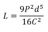
Where
C = Minimum required discharge capacity, pounds of air per minute
d = Internal diameter of pipe, inches
L = Length of discharge pipe, inches
P = (rated pressure in psig x 1.1) + 14.7
2012 International Mechanical Code §1105.8 Ammonia discharge.
Pressure relief valves for ammonia systems shall discharge in accordance with ASHRAE 15.
ASHRAE 15-2010 §9.7.8.5
The maximum length of the discharge piping installed on the outlets of pressure-relief devices and fusible plugs discharging to the atmosphere shall be determined by the method in Normative Appendix E. See Table 3 for the flow capacity of various equivalent lengths of discharge piping for conventional relief valves.
ASHRAE 15-2010 Appendix E Allowable Equivalent Length of Discharge Piping
The design back pressure due to flow in the discharge piping at the outlet of pressure-relief devices and fusible plugs, discharging to atmosphere, shall be limited by the allowable equivalent length of piping determined by Equation E-1 (I-P or SI). See Table 3 for the flow capacity of various equivalent lengths of discharge piping for conventional relief valves.
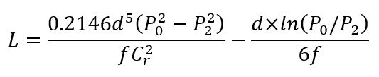
Where
L = equivalent length of discharge piping, ft (m)
Cr = rated capacity as stamped on the relief device in lb/min (kg/s), or in SCFM multiplied by 0.0764, or as calculated in Section 9.7.7 for a rupture member or fusible plug, or as adjusted for reduced capacity due to piping as specified by the manufacturer of the device, or as adjusted for reduced capacity due to piping as estimated by an approved method
f = Moody friction factor in fully turbulent flow
d = inside diameter of pipe or tube, in.
P2 = absolute pressure at outlet of discharge piping, psi
P0 = allowed back pressure (absolute) at the outlet of pressure relief device, psi
As can be seen above, two ammonia refrigeration systems built in 2012 could have different relief valve discharge termination piping designs depending on whether the IMC or the UMC was used as RAGAGEP. Consider the hypothetical scenario of a 250 psig relief valve with a rated capacity of 100 lb/minair equipped with 2” schedule 40 outlet piping. Comparing the equations above results in the following allowable length of discharge piping:
- UMC: 14.8 ft
- IMC: 83.9 ft
Refer to Appendix B for complete analysis.
Conflict 2: Special Discharge Requirements for Ammonia
There has been a two decade RAGAGEP conflict between the UMC and the IMC relative to relief valve discharge piping location. Since 1994, this conflict has resulted in the installation of ammonia diffusion tanks on ammonia refrigeration systems in California and other jurisdictions adhering to the UMC, while jurisdictions following the IMC have terminated relief valves directly to atmosphere.
2012 Uniform Mechanical Code §1120.0 Ammonia Discharge
Ammonia shall discharge into a tank of water that shall be used for no purpose except ammonia absorption. Not less than 1 gallon (4 L) of fresh water shall be provided for each pound (kg) of ammonia that will be released in 1 hour from the largest relief device connected to the discharge pipe…
2012 International Mechanical Code §1105.8 Ammonia Discharge.
Pressure relief valves for ammonia systems shall discharge in accordance with ASHRAE 15.
ANSI/ASHRAE 15-2013 §9.7.8.2 Ammonia Discharge.
Ammonia from pressure-relief valves shall be discharged into one or more of the following:
a. The atmosphere, per Section 9.7.8
b. A tank containing one gallon of water for each pound of ammonia (8.3 liters of water for each kilogram of ammonia) that will be released in one hour from the largest relief device connected to the discharge pipe. The water shall be prevented from freezing. The discharge pipe from the pressure-relief device shall distribute ammonia in the bottom of the tank but no lower than 33 ft (10m) below the maximum liquid level. The tank shall contain the volume of water and ammonia without overflowing.
c. Other treatment systems that meet the requirements of the AHJ
This RAGAGEP conflict has been partially resolved in the 2015 versions of the UMC and the IMC. The 2015 UMC has removed all references to diffusion tanks, but unfortunately “special discharge requirements” still apply to ammonia refrigeration systems. While diffusion tanks have been removed as a requirement, 2015 UMC §1114.1 now requires all discharge to atmosphere to be through a flaring device unless the “Authority Having Jurisdiction determines upon review of a rational engineering analysis that fire, health, or environmental hazards will not result from the proposed atmospheric release.”
Best Practices
The key to addressing RAGAGEP conflicts is to clearly document the codes and standards that were followed in the design and installation of the ammonia refrigeration system. Often this information will be contained in the “notes” section of the engineering drawings, but other forms of documentation are also acceptable. Appendix C includes a sample form that can be used to document the codes and standards used to design and install a refrigeration system.
Additionally, clear communication regarding RAGAGEP conflicts is essential. The communication should include, but not be limited to the following:
- Owner
- Authority Having Jurisdiction (AHJ)
- Design Engineer
- Contractor
- Consultant/PHA Team
Leave a Reply