
Refrigeration Cycle: Capacity Control
Most refrigeration systems are subject to variable system loads caused by weather and product load fluctuations. For this reason, refrigeration systems must be capable of operating at “part load”. Engineers and plant operators achieve this, in part, by utilizing capacity control in compressors.
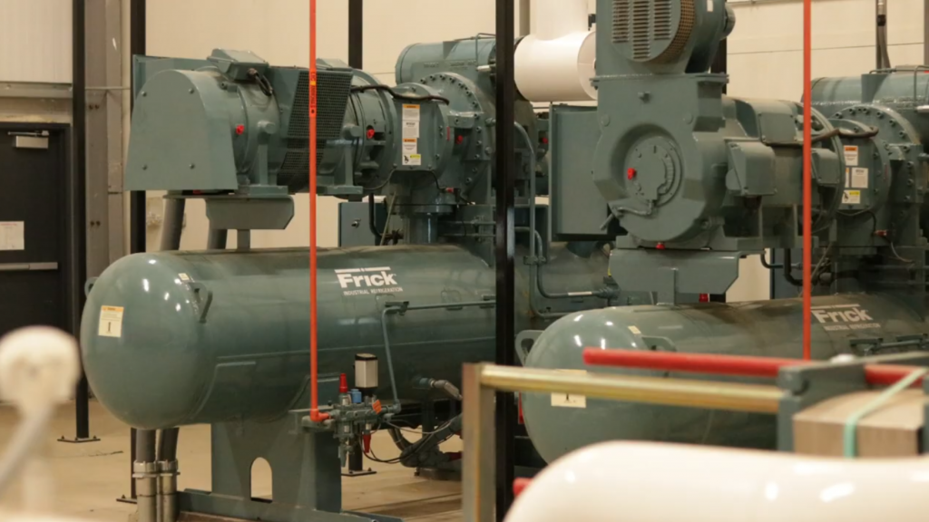
In reciprocating compressors, capacity control is accomplished by what is called “cylinder unloading”. Cylinder unloading is accomplished by forcing one or more cylinder suction valves “open”. During the intake stroke, vapor will be drawn into the cylinder, but since the suction valve is forced open, no compression will take place during the compression stroke and the vapor will simply exit through the suction valve from which it entered.
Unloading in reciprocating compressors typically occurs in two-cylinder increments. For example, a six-cylinder compressor could unload down to four or two cylinders corresponding to 66.7% or 33.3% capacity. An eight-cylinder compressor could unload down to six, four, or two cylinders or 75%, 50%, or 25% capacity.
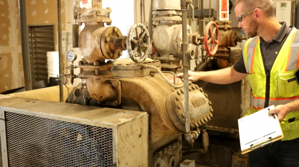
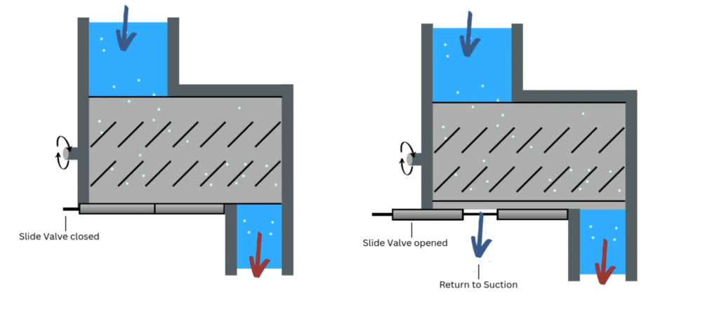
In screw compressors, capacity control is typically achieved by employing what is called a “slide valve”. The slide valve is located between the rotors and consists of a sliding member that covers an opening that allows gas to be vented back to suction. During part-load conditions, the slide will move to uncover the opening which will decrease the amount of vapor that is compressed. Slide valves allow screw compressors a continuous range of unloading, typically from 100% down to 10% of their full capacity.
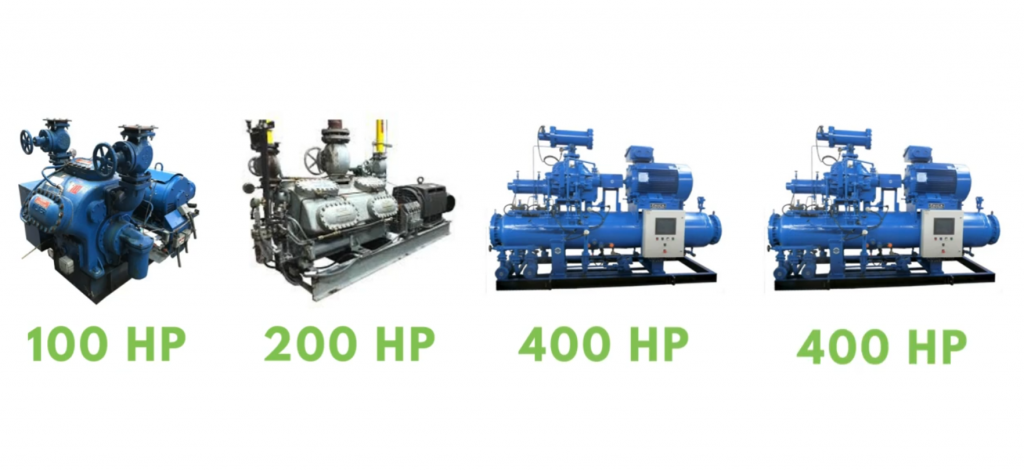
Operating a compressor “unloaded” is less efficient than operating at full capacity. For this reason, larger systems will often have multiple compressors with different capacities. For example, let’s consider a hypothetical system with a 100 HP, 200 HP, and two (2) 400 HP compressors. When the system load is minimal, the 100 HP compressor would be the primary machine. When the load exceeds the 100 HP compressor capacity, the 200 HP compressor would take over and the 100 would meet any excess capacity needs. For larger loads, one or both of the 400 HP compressors may be required. The most efficient operation will have as many compressors as possible operating fully loaded and the 100 HP compressor “trimming” the remaining load. The compressor performing that function is often referred to as the “trim compressor”. A more energy-efficient option for screw compressor capacity control is the utilization of a variable frequency drive, or VFD, on the compressor motor. VFDs modify the frequency of the power supplied to the motor, which in turn, lowers the rotational speed. The beauty of VFDs is that the power consumption varies as a cube of the motor speed. This means that if we reduce the motor speed to one-half of the design speed, the power consumed will be reduced to one over two cubed, or ⅛ of the original power. VFDs, however, are expensive and generally are not justified if a compressor will operate fully loaded most of the time. For this reason, systems with multiple compressors may only equip the trim machine with a VFD.
Leave a Reply