PSI Explained: Piping and Instrument Diagrams (P&IDs)
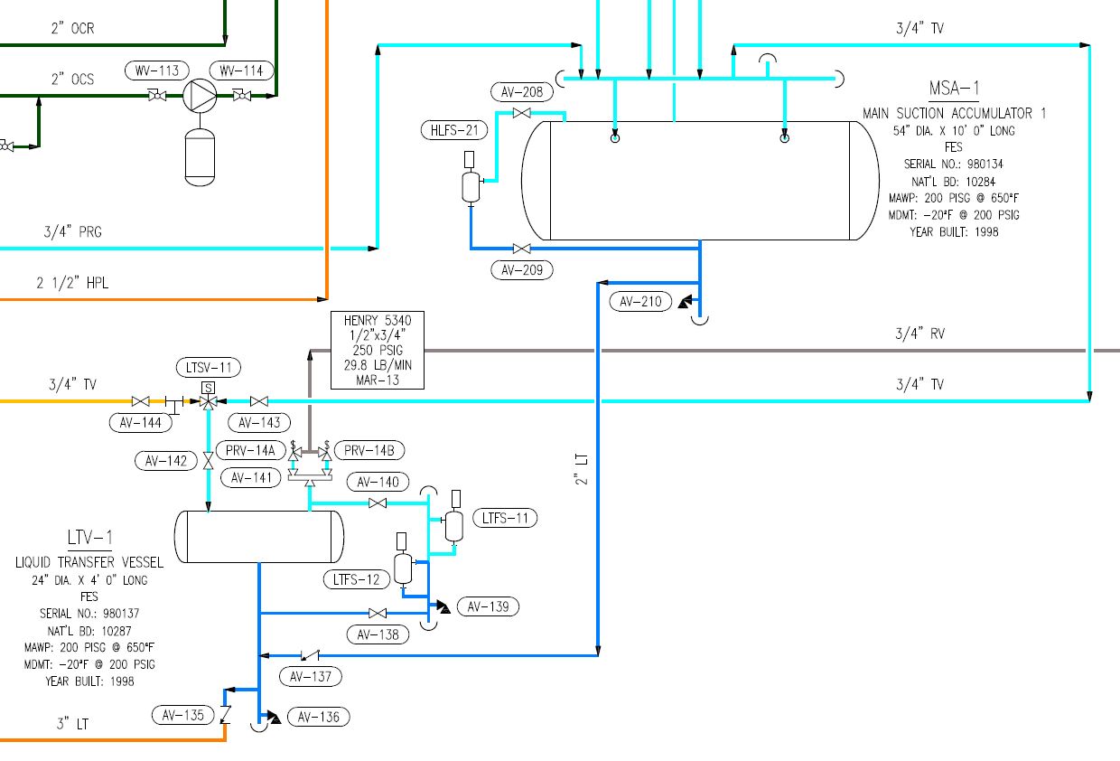
If Process Safety Information is the foundation of a PSM program, then Piping and Instrument Diagrams (P&IDs) are the cornerstone. An engineer or technician that desires to familiarize with a chemical process will often first turn to the P&IDs because of the detailed equipment information included on the diagrams. P&IDs must include at least the following:
- Process Equipment
- Piping
- Valves
- Control Valves
- Relief Valves
- Instruments (gauges, sensors, transducers)
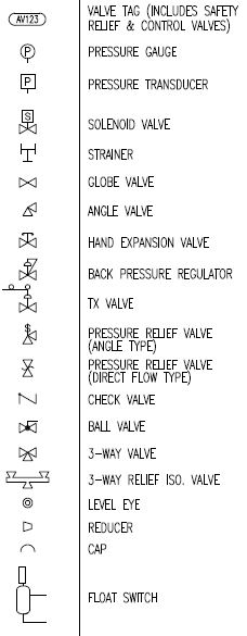
A good P&ID will be equipped with a clear legend of symbols to assist in diagram interpretation.


P&IDs utilize detailed annotations to describe the pipes and equipment. Examples of typical annotations include:
- Equipment name
- Equipment specifications
- Valve/Equipment Tag ID#
- Pipe service
- Flow direction
- Page connectors

It can be difficult to find a P&ID that is 100% accurate, but that should not prevent us from attempting to achieve that status. Regular review of P&IDs is essential to anyone who desires to be familiar with a system and since PSM requires that that employees be trained in a “overview of the process”, what better opportunity to obtain an “overview of the process” than to walk the system with a P&ID in hand.
IIAR published Appendix A: Guidelines for Preparation of Ammonia Refrigeration Diagrams to the Ammonia Refrigeration Piping Handbook in 2012. This appendix outlines the best practices for preparing an ammonia refrigeration P&ID. Page A-6 includes a helpful list of diagram format recommendations. I have paraphrased the list below:
- Diagram may be a simple mechanical schematic. Equipment may be laid out in a flow-related format.
- Equipment should be graphically represented as close as possible to reality.
- P&ID is not required to be limited to a single drawing. Avoid over-crowding any single drawing.
- Equipment may be shown schematically with designated symbols and abbreviations.
- Line sizes and line designations including valves and controls should be shown using uniform symbology.
Line continuations may continue from drawing to drawing. When this is the case, a continuation symbol must be used to identify the flow direction and the page where the line continues.

Leave a Reply