Pipe Wall Thickness
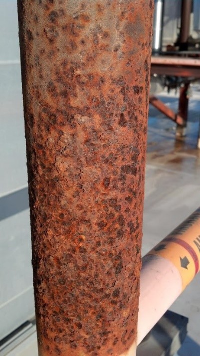 Pipes are one of the areas of an ammonia refrigeration system most vulnerable to leak. Systems often have hundreds, or even thousands of feet of ammonia pipes serving a variety of purposes. Historically, IIAR Bulletin No. 110 has been the RAGAGEP which governs ammonia pipe inspections and maintenance. §6.7.1 requires that:
All uninsulated piping and associated components such as flanges and supports shall be inspected annually for any damage to or deterioration of the piping or its protective finish; take remedial action where necessary. Areas affected by slight corrosion should be cleaned off and appropriately treated before reinstating the protective finish. Deeper pitting or loss of metal, where considered by subjective assessment to be greater than 10% of original wall thickness, should be checked accurately by using techniques such as ultrasonic measurements. If such wall thinning is confirmed, expert advice should be sought, for example from an authorized inspection agency, to determine the need for, and the extent and timing of, any replacements.
The “expert advice” referenced in §6.7.1 has lacked uniformity over the years, partially due to lack of published information regarding best practices for replacement of ammonia pipes based on wall thickness. In April 2016, Industrial Refrigeration Consortium published Principles and Practices of Mechanical Integrity Guidebook for Industrial Refrigeration Systems.
This guidebook includes recommended actions (Table 4-6) to be taken as a result of the measured wall thickness. A summary of the recommended actions is included below:
| Level | Criteria | Flag | Action Required/Comments |
| 1 | t ≤ 0.3 x tnom | Repair or replace unless engineering analysis demonstrates that the pipe is fit for continued service | |
| 2 | 0.3 x tnom ≤ t < talert | Perform a detailed engineering analysis to determine tmin for the portion of the piping system in question. Repair, replace, or arrest corrosion and continue service based on the results of the analysis. | |
| 3 | talert ≤ t < 0.875 x tnom | Piping can continue in operation. As the thickness approaches tmin, increase the frequency of pipe inspections. | |
| 4 | t ≥ 0.875 x tnom | Piping can continue in operation. |
The alert thickness (talert) referenced in the table was derived from API RP 574 and in most cases, represents 40%-60% material loss compared to nominal thickness (tnom). In the event that a “detailed engineering analysis” is employed, then either ASME B31.3 or ASME B31.5 would need to be referenced which both include a variation of the following equation:
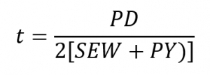
Where:
P = internal design pressure
D = outside diameter of pipe
S = stress value for material
E = quality factor
W = weld joint strength reduction factor (1.0 for refrigeration applications)
Y = coefficient (0.4 for steel pipes)
The following example demonstrates tmin for an 8” Schedule A53 Grade B ERW suction pipe:
P = 150 psi (design suction pressure)
D = 8.625 in (outer diameter of an 8” pipe)
S = 20 ksi = 20,000 psi (from ASME B31.3-2016 Table A-1)
E = 0.85 (for A53 ERW pipe, from ASME B31.3-2016 Table A-1B)
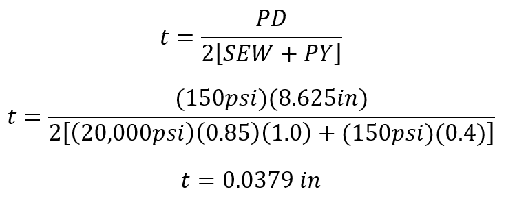
It is worth emphasizing that the nominal thickness (tnom) of an 8” Schedule 40 pipe is 0.322 inches which is 850% of the calculated minimum thickness.
Leave a Reply